Current version: 7.4.10.52
Manual mode.
Greetings, colleagues!
This article will be addressed to all holders of cutting plotters, except those, who has automatic contour cutting function.
The main objective is the combination of the printed image and contours (which must be cutted on the printed image).
Well, who thinks that it is very simple - it is not always assured - very often print comes with linear distortion on all axes - for example, if you sending rectangle , the output can be trapezoid - and this distortion must be corrected.

In fact, this task is performed not by eCut. eCom makes it - secondary program that worked through com port - but new version of this program can connect to plotter not only through com port , but also through printer driver installed in your system. Well enough theory - go to practice. Now I will tell you how to prepare files for printing and cutting . As well as how to prepare a file for cutting if the seal has already been done ( there are some subtleties ) . And then I"ll show how eCom works.
This option is compatible (in principle) , with any kind of crop marks. The main goal that cutting object fit printed object in crop mark points. I will explain the example of several types of printed crop marks :
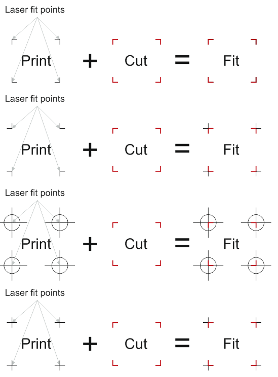
In the picture:
Print - printed crop marks.
Cut - cutted crop marks.
Fit - combination of print and cut objects.
Laser fit points - point in cropmark that must fit cutting corner.
On an example of perfectly clear that cutting edge (corners red dots ) coincide with the characteristic points on the seal ..
Link to this example.
Now, directly contour cutting.
The material should be placed in the plotter so that all printed objects must be in the cutting area , and the most proximal crop mark must be near (1cm) origin.
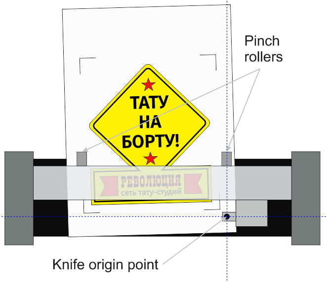
By guide lines seen that all the objects ( including the crop marks) lie in the plotter cutting are - i.e. to the left of and above the initial point.
Once the material is placed , set the plotter to receive data (if necessary) and open the file of contour cutting .
Select the object that will be cut and start cutting with eCut:
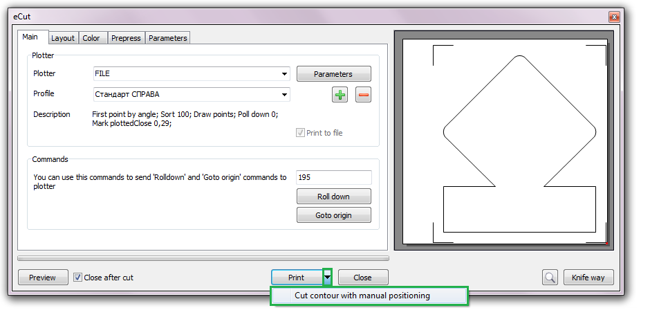
In prepress tab you need to disable ROLL DOWN feature, or set it to ZERO.
Everything is as usual with one small BUT - do not click Print, click on little array near Print button and select "Contour cutting with manual positioning." If you do not see this button - click right mouse button on "Print" button and you"ll get it.
After pressing , eCut do its work and eCom will start.
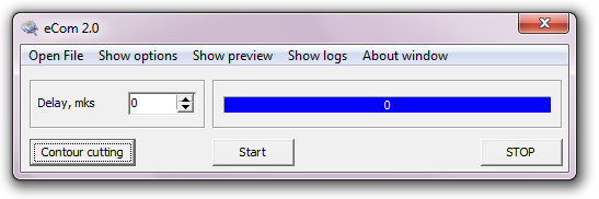
If you have not configured eCom - then you need to configure it first(Press "Show options" button, set Communication method and check COM port settings or Printer name). If eCom is configured , simply click the button "Contour cutting" ( a warning dialog box - agree ) , and you"ll see its window :
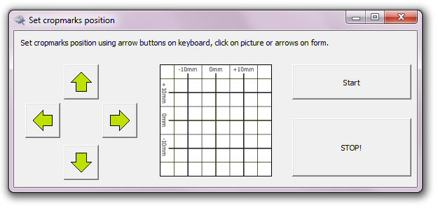
That, essentially, is the culmination of the entire process - bypassing the checkpoint and correction . Manage and specify plotter control points in three ways:
1. You can just click on the arrow.
2. You can use keyboard arrrows.
3. You can poke the mouse on the image , if the crop mark is within 2cm from the point .
In a few words that have to do now - after pressing the START button , you will need to provide the nearest reference point - a point number one. Bypass points is clockwise .
Further, clicking "Set CropMark # 1" plotter goes to the second control point - it also needs to fit , confirm by pressing the "Set CropMark # 2 " and so on up to the fourth point.
After pressing the "Set CropMark # 4 and start" plotter returns to the origin and begin cutting considering distortion.
Note:
If your plotter has a laser pointer, and its offset can be specified in the settings of the plotter , all this needs to be done by turning on the laser pointer (usually panel plotter has a corresponding button).
If there is a pointer at the plotter and the offset ( the distance from the tip of the knife to the projected laser dot ) in the plotter can not be specified , it can be done in eCom. To do this in the settings (Show options) has parameters :
Laser offset DX - horizontal offset
Laser offset DY - vertical offset
Through trial and error , these parameters must be chosen . Here "s what you need to remember - this offset you have to specify in plotter points - usually it is 40 points per 1 mm , but not always.
Well, actually , that"s all. If you have questions / suggestions - write, discuss .
[Nesting][Cut/Plot + contour cutting][Perimeter][Area][Cost][Time][Weeding lines][Multiply][Rectangle nesting][LEDs][Neon][Draft][Central line][Smart divide][Connect opened paths][Fillet][Find intersections][Find duplicates][Search shapes][Create SignBox][Create lines][Create grid][Create cropmarks][Reduce nodes][Effects][Edge roll][Contour cutting file][Separate curve][Remove duplicated edges][Slice object][Eyelets][Create carrier (boundbox)][Align and Distribute][Set size][CAD functions][DXF Export][Replace][Reference scale][Create bridges][Variable][Hotwire cutting][Route optimizer][Finger joint box][Finger joint shape][Volume calculator][Door panels][G codes][Liquid acrylic][Scripts][Finger joint change size]
Other projects: rStones AI nesting eCut for Illustrator eCut for MAC OS
since © 2007 eCut.